EN

IA2000 5G Fronthaul Semi-active Device
U2 DC subframe
U3 DC subframe
U5 AC subframe
U5 AC subframe-2
U5 DC subframe
IA2000 5G Fronthaul Semi-active Device
IA2000 is a 5G fronthaul wavelength division product launched by FiberHome Telecommunication. This product includes local side frame device IA2000 U2, IA2000 U3, IA2000 U5 and remote box passive module. Coarse/dense wavelength division technology is used to meet various distance and bandwidth networking requirements of forward transmission, which can effectively reduce the optical fiber demand in fronthaul field. The device is introduced from the following aspects.
IA2000 is a 5G fronthaul wavelength division product launched by FiberHome Telecommunication. This product includes local side frame device IA2000 U2, IA2000 U3, IA2000 U5 and remote box passive module. Coarse/dense wavelength division technology is used to meet various distance and bandwidth networking requirements of forward transmission, which can effectively reduce the optical fiber demand in fronthaul field. The device is introduced from the following aspects.
Product Application
Brief introduction of device
IA2000 is located in the 5G fronthaul network, and a star network topology can be set up according to specific scenarios, that is, one local side corresponds to multiple remote modules; it also supports point-to-point networking applications.
IA2000 features:
Flexible configuration of 6-wave or 12-wave CWDM, 12-wave MWDM system or 40-wave DWDM system to solve the problem of shortage of fronthaul optical fibers
Local side device supports docking multiple far-ends in multiple line directions, and supports 1+1 protection of each line
It supports carrier class network management, such as configuration, alarm and performance management
CWDM system supports optical power monitoring of branch optical channel and optical power monitoring of the main and standby lines both in transmitting and receiving directions;
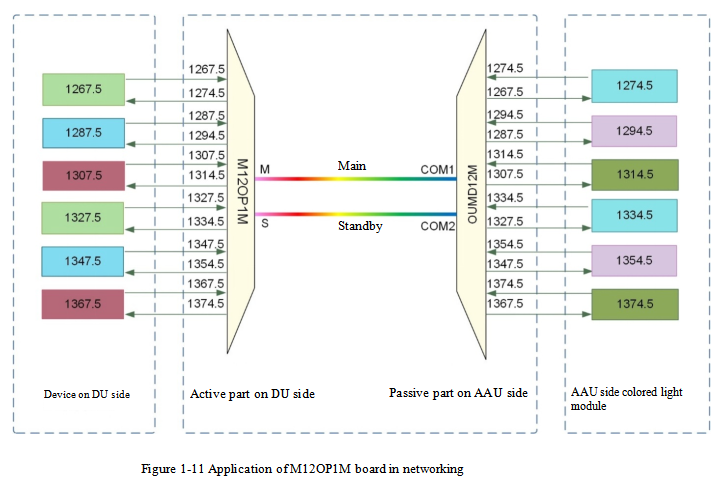
MWDM supports top modulation OAM of colored light modules on DU side and AAU side, and MWDM board supports the encoding and decoding of OAM information (network management realizes the monitoring of OAM information of optical modules based on this).
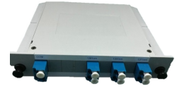
IA2000 series includes U2, U3 and U5 devices, and the external view of each device is shown in the following figure.

The remote passive device (i.e., the wave combining and dividing module) of IA2000 is usually installed in the user distribution box, including multiple wavelength sub-model; The external view of each model of remote device is basically the same. The OUMD6 board is taken as an example in the following figure.
Networking Application
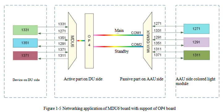
When IA2000 is used for local and remote networking applications, the local side is docked with remote device (DEMUX wave mixing and dividing module) through mixing and dividing panels for various wavelength (such as MDU6 and MDU12 panels) and optical line protection panel (OP4 panel). The networking application is shown in the following two figures.


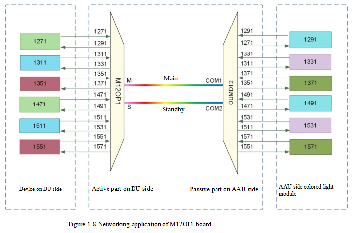
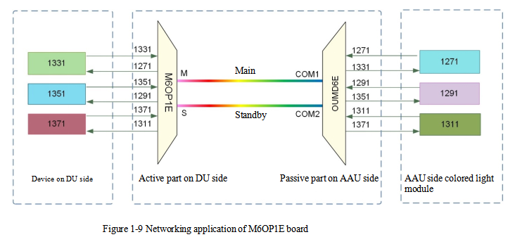
When IA2000 is used for local and remote networking applications, the local side can be docked with remote device (OUMD wave mixing and dividing module) through M6OP1E panel, M12OP1E panel and M12OP1M panel (equipped with optical line protection panel), and the networking application is shown in the following figures.

When IA2000 is applied in point-to-point DWDM networking, the typical networking application of each chassis is shown in the following figure.

Product functions and features
The features of wavelength division, protection and network management of IA2000 products is introduced.
Wavelength division features of CWDM/MWDM/DWDM
IA2000 supports flexible configuration of CWDM, MWDM and DWDM, which can meet the diversified requirements for construction cost of 5G fronthaul network, transmission distance and transmission capacity.
CWDM system specification
IA2000 can be used for flexible configuration of 6-wave or 12-wave CWDM system.
Configuration of 12-wave CWDM system: 12-wave × 10Gbit/s, first 6 waves × 25Gbit/s + last 6 waves × 10Gbit/s
Configuration of 6-wave CWDM system: The corresponding wave bands, wavelength intervals and maximum transmission capacity of 6-wave × 25Gbit/s and 6-wave × 10Gbit/s are shown in the following table
TABLE 1-1 CWDM system specification
| Project | CWDM system |
| Single wave rate (bit/s) | 25G and 10G |
| Applicable optical fiber | G.652, G.653 and G.655 optical fibers |
| Wave bands used in the system (nm) | 1271~1571 |
| Number of available wavelengths (pcs) | 12 |
| Minimum wavelength interval (nm) | 20 |
| Maximum transmission capacity (G) | 210 |
The wavelengths applied in CWDM system are shown in the following table.
Table 1-2 Wavelength table applied in CWDM system
| SN | Wavelength (nm) | SN | Wavelength (nm) |
| 1 | 1271.00 | 7 | 1471.00 |
| 2 | 1291.00 | 8 | 1491.00 |
| 3 | 1311.00 | 9 | 1511.00 |
| 4 | 1331.00 | 10 | 1531.00 |
| 5 | 1351.00 | 11 | 1551.00 |
| 6 | 1371.00 | 12 | 1571.00 |
MWDM system specification
IA2000 can be used for the configuration of 12-wave x 25Gbit/s MWDM system. The corresponding wave bands, wavelength intervals and maximum transmission capacity are shown in the following table.
Table 1-3 MWDM system specification
| Project | MWDM system |
| Single wave rate (bit/s) | 25G |
| Applicable optical fiber | G.652, G.653 and G.655 optical fibers |
| Wave bands used in the system (nm) | 1267.5~1374.5 |
| Number of available wavelengths (pcs) | 12 |
| Minimum wavelength interval (nm) | 7 |
| Maximum transmission capacity (G) | 300 |
The wavelengths applied in MWDM system are shown in the following table.
Table 1-4 Wavelength table applied in MWDM system
| SN | Wavelength (nm) | SN | Wavelength (nm) |
| 1 | 1267.5 | 7 | 1327.5 |
| 2 | 1274.5 | 8 | 1334.5 |
| 3 | 1287.5 | 9 | 1347.5 |
| 4 | 1294.5 | 10 | 1354.5 |
| 5 | 1307.5 | 11 | 1367.5 |
| 6 | 1314.5 | 12 | 1374.5 |
DWDM system specification
IA2000 can be used for the configuration of 40-wave x 10Gbit/s DWDM system. The corresponding wave bands, wavelength intervals and maximum transmission capacity are shown in the following table.
Table 1-5 DWDM system specification
| Project | DWDM system |
| Single wave rate (bit/s) | 10G |
| Applicable optical fiber | G.652, G.653 and G.655 optical fibers |
| Wave bands used in the system (nm) | 1529.55~1560.61 |
| Number of available wavelengths (pcs) | 40 |
| Minimum wavelength interval (nm) | 0.8 |
| Maximum transmission capacity (G) | 400 |
The wavelengths applied in DWDM system are shown in the following table.
Table 1-6 Wavelength table applied in DWDM system
| SN | Wavelength (nm) | Centre frequency (THz) | SN | Wavelength (nm) | Centre frequency (THz) |
| 1 | 1560.606 | 192.1 | 21 | 1544.526 | 194.1 |
| 2 | 1559.794 | 192.2 | 22 | 1543.73 | 194.2 |
| 3 | 1558.983 | 192.3 | 23 | 1542.936 | 194.3 |
| 4 | 1558.173 | 192.4 | 24 | 1542.142 | 194.4 |
| 5 | 1557.363 | 192.5 | 25 | 1541.349 | 194.5 |
| 6 | 1556.555 | 192.6 | 26 | 1540.557 | 194.6 |
| 7 | 1555.747 | 192.7 | 27 | 1539.766 | 194.7 |
| 8 | 1554.94 | 192.8 | 28 | 1538.976 | 194.8 |
| 9 | 1554.134 | 192.9 | 29 | 1538.186 | 194.9 |
| 10 | 1553.329 | 193.0 | 30 | 1537.397 | 195.0 |
| 11 | 1552.524 | 193.1 | 31 | 1536.609 | 195.1 |
| 12 | 1551.721 | 193.2 | 32 | 1535.822 | 195.2 |
| 13 | 1550.918 | 193.3 | 33 | 1535.036 | 195.3 |
| 14 | 1550.116 | 193.4 | 34 | 1534.25 | 195.4 |
| 15 | 1549.315 | 193.5 | 35 | 1533.465 | 195.5 |
| 16 | 1548.515 | 193.6 | 36 | 1532.681 | 195.6 |
| 17 | 1547.715 | 193.7 | 37 | 1531.898 | 195.7 |
| 18 | 1546.917 | 193.8 | 38 | 1531.116 | 195.8 |
| 19 | 1546.119 | 193.9 | 39 | 1530.334 | 195.9 |
| 20 | 1545.322 | 194.0 | 40 | 1529.553 | 196.0 |
Protection function
The network management board protection, power plate protection and optical line protection functions of IA2000 are introduced.
Network management board protection
Introduction
IA2000 supports 1+1 redundancy protection of network management board. If the main network management board fails, the standby board will replace the main board, to ensure the normal operation of the system.
As shown in Table 1-7, U2, U3 and U5 DC subframes of IA2000 provide 1+1 protection for network management panel (i.e., the network management panels in the two slots will act as main and standby for each other). If the main panel fails, the standby panel will immediately replace the main panel and enter the working state.
Table 1-7 Slots of network management board correspond to
| DC subframe | Network management board | Slot |
| U2 | NM2A | 7, 8 |
| U3 | NM3A | 11, 12 |
| U5 | NM3A, XCM5A Note 1 | 18, 19 |
| Note 1: When it's configured as a CWDM/MWDM system, U5 subframe uses NM3A board; When it's configured as a DWDM system, U5 subframe uses XCM5A board. | ||
Prompt:
In the 1+1 protection of network management board, the network management board that is powered on first and works normally is the main board, and the other one is the standby board.
If the two network management panels in the two slots are powered on at the same time, U2 DC subframe defaults the panel in slot 7 as the main panel, U3 DC sub-frame defaults the panel in slot 11 as the main panel,and U5 DC sub-frame defaults the panel in slot 18 as the main panel.
Protection parameter
Table 1-8 1+1 protection of network management board
| Parameter | Description |
| Type of protection | 1+1 protection of network management board |
| Return mode | Non-return type |
Function realization
The main and standby network management boards exchange status information through the monitoring lines between boards to realize the switching between the main and standby boards.
Protection switching process of main and standby network management boards
If the main board is not in place or invalid, or main-standby board switching command sent from the network management is received, the standby board will be notified through the monitoring line between main and standby boards. At this time, the standby board will replace the former main board to become the current main board, enter the working state, and complete the network element management function.
The former main board will enter the standby state when the fault is eliminated. The former main board will not return to the working state unless the current main board fails or manual switching command is received.
Data synchronization mode of main and standby network management boards
In order to ensure the normal operation of standby board when it is switched to the working state, it must be synchronized with the configuration data of the main board in real time. There are two ways to synchronize the configuration data: active synchronization and passive synchronization:
Active synchronization: The standby board actively inquires the main board whether the configuration is changed, and at the same time transmits the configuration and verification information to the main board. After receiving the information, the main board will compare it, and sends the configuration information to the standby board for data synchronization if the information is inconsistent. Active synchronization is adopted when the standby board is just powered on.
Passive synchronization: The main board transmits the data to the standby board as soon as it receives the data from the network management. Passive data synchronization of the main and standby boards is adopted when the configuration is distributed to the device from network management.
Switching trigger conditions
There are two trigger conditions for protection switching of 1+1 network management boards:
Automatic switching: If the standby board receives the message that the main board is not in place or invalid, it will automatically start switching. Human intervention is not required in the switching process
Manual switching: Generally, when it is necessary to test whether the network management board can be switched normally, the network management board can be plugged and unplugged manually or to realize the switching by issuing the command of switching main and standby boards from the network management
Power plate protection
The two power plates of U2, U3 and U5 subframes of IA2000 are inserted in the dedicated slots and acts as 1+1 protection for each other.
Both the main and standby power plates can be connected with a -48V power from PDP to supply other chassis. That is, any power plate failure will not affect the normal power supply of the chassis in the subframe.
1+1 optical line protection
1+1 optical line protection can be implemented in the following three ways:
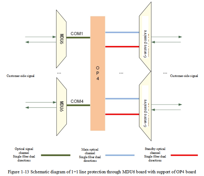
The 1+1 optical line is protected by the double receiving and selective transmission function of OP4 board, with supports of MDU6 board and MDU12 board
OP4 board first detects whether the main and standby optical lines are in normal state and selectively sends the service signal to the normal optical line. The device on the opposite end receives the optical signal from the main and standby lines at the same time, thus protecting the lines at both sides of the service. Each OP4 board can realize 1+1 protection of 4 groups of lines.
M6OP1 board, M12OP1 board, M12OP1M board, M6OP1E board and M12OP1E board have their own optical line protection function, double receiving and selective transmission of luminous signals, thus realizing the 1+1 optical line protection
In the networking application of DWDM, the 1+1 optical line protection is realized by using the double receiving and selective transmission function of OCP board
The 1+1 optical line protection is realized through OP4 board and M6OP1 series boards
Function realization
As shown in Figure 1-13 and Figure 1-14, the line 1+1 protection is introduced by taking MDU6 board supported by M6OP1 board and by OP4 board respectively as an example.
The 1+1 line protection is introduced with the example of M6OP1 board, as shown in Figure 1-14.

Transmission direction
OP4 board cooperates with MDU6 board or M6OP1 board to combine the signals coming in from customer end into one optical signal. OP4 board optical switch or M6OP1 board selectively sends the optical signal to the main or standby optical channel and transports it to the opposite end by detecting the state of the main or standby line.
Under normal circumstances, OP4 board or M6OP1 board will select the main line to send service signals to the opposite end.
If OP4 board or M6OP1 board detects that the main line breaks down and the standby line is normal, it will send service signals to the opposite end through the standby line.
When the main line returns to normal, it will be judged whether to use the main line to send service signal according to the protection recovery type pre-configured on the network management.
Receiving direction
The optical interfaces in the main and standby lines of remote device receive optical signals transported by the line at the same time.
Switching trigger conditions
When the optical power of optical signal either in the main line or standby line exceeds the threshold value, the working line will be switched.
Protection parameter
| Parameter | Description |
| Return mode | Return type and non-return type |
| Return time (seconds) | The default value is 0, and it can be set through network management |
1+1 optical line protection is realized through OCP board
Introduction
1+1 optical line protection between local side and remote end is realized by using the dual transmission and selective receiving function of OCP board.
Function realization
The schematic diagram of 1+1 line protection, with OCP board cooperating with MDU8 board and VMU40_E/ODU40_E board, is shown in Figure 1-15.

Local transmission direction
The wave-combined signal of base station 8CH-MUX module is divided by MDU8 board and then mixed by VMU40_E board, and it becomes 1 channel of optical signal and enters the IN port of OCP board. Then it is divided into two parts after passing through the optical splitter of OCP board, and then output to the line through TXA (main) and TXB (standby) ports.
Opposite end receiving direction
The optical signals of the main and standby lines are respectively accessed from the RXA and RXB ports of the OCP board and
5% of the light is separated from the accessed signal and sent to the optical power detection module of the board.
The optical power detection module feeds back the detection result to the optical switch of OCP board for selection and reception of main optical signals and standby optical signals, and the selectionand reception signals are output from the OUT port.
Switching trigger conditions
When the optical power of optical signal either in the main line or standby line exceeds the threshold value, the working line will be switched.
Protection parameter
| Parameter | Description |
| Return mode | Return type and non-return type |
| Return time (seconds) | The default value is 0, and it can be set through network management |
Carrier class network management
Carrier class network management functions of IA2000 device are shown in Table 1-9.
Table 1-9 Carrier class network management function
| Classification | Function |
| Configuration management | Support the setting of OLP protection mode |
| Support the setting of OLP protection return mode | |
| Support the setting of OLP protection switching return time | |
| Support the setting of high and low threshold values of receiving and emitting power | |
| In DWDM application, it supports the optical power automatic adjustment of VMU board channel | |
| performance management | Support reporting single board temperature |
| Support reporting OLP protection status information | |
| Support monitoring optical interface status | |
| Support reporting the received and transmitted optical power of port | |
| Support 15-minute, 24-hour granular performance statistics | |
| Supports querying the status of main and standby channels | |
| Alarm management | Support fault alarm of power plate |
| Support abnormal temperature alarm of single board | |
| Support dislocation alarm of service board | |
| Support over-limit alarm of input and output optical power | |
| Support port down status alarm | |
| Support device cold and hot start failure alarm |